
Description
Product Overview
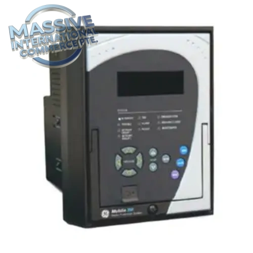
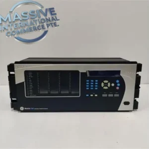
The 350-E-P1-G1-H-E-E-N-P-SN-D is a fully configurable GE Multilin 350 series feeder protection relay for medium-voltage distribution feeders. It integrates protection, metering, fault recording, sequence of events and communication functions. The long part number is a custom build code where each segment defines CT rating, I/O type, communication, power supply and hardware options. Widely used in power substations, industrial plants, mining and petrochemical distribution networks for overhead line and cable feeder protection.
Technical Specifications
| Item | Parameter |
|---|---|
| Manufacturer | GE Multilin (GE Vernova) |
| Part Number | 350-E-P1-G1-H-E-E-N-P-SN-D |
| Product Type | Feeder Protection & Control Relay |
| Series | 350 Multilin |
| Phase CT Rating | P1 = 1 A secondary phase current input |
| Ground CT Rating | G1 = 1 A ground current input |
| Output Type | H = Hard contact electromechanical outputs |
| Communication | E = Ethernet; E = second communication port |
| Power Supply | P = 125 V DC nominal auxiliary power |
| Enclosure / Option | SN = Standard front panel, D = drawout case |
| Rated Frequency | 50 / 60 Hz auto detect |
| Operating Temperature | -40°C ~ +85°C |
| Protection Functions | 50/51 phase overcurrent, 50N/51N ground overcurrent, breaker failure, thermal overload, undervoltage/overvoltage, frequency protection, cold load pickup |
| Data Recording | Fault waveform capture, event sequence recorder, demand metering |
| Protocols | Modbus TCP, DNP3 over Ethernet, IEC 61850 optional |
| Mounting | Panel mount drawout case |
Key Features
- All-in-one feeder protection combining ANSI protection elements, power quality metering and breaker control logic.
- Dual Ethernet ports support redundant network connection for substation SCADA and DCS integration.
- Drawout chassis design, allows relay core replacement without rewiring CT/VT secondary circuits.
- High resolution fault oscillography and sequence of events (SOE) with millisecond timestamp for post-fault analysis.
- Built-in HMI front panel with LCD, local breaker control, setting view and alarm indication.
- Flexible logic editor to customise interlocks, recloser control and breaker monitoring.
- Self-monitoring diagnostics with hardware fault alarm to reduce unplanned outage risk.
Installation & Testing Notes
- CT and VT secondary wiring must follow substation safety rules; short CT terminals before wiring.
- Confirm auxiliary DC supply matches P option (125VDC) before powering up.
- Configure relay settings via GE EnerVista 350 setup software.
- Perform secondary injection test to verify overcurrent protection pickup, timing and trip output.
- Check Ethernet communication, SOE recording and fault capture during commissioning.
- Inspect front panel, drawout connectors and terminal blocks for corrosion or pin damage before spare deployment.
FAQ
Q: What does P1 and G1 mean in this part number? A: P1 means phase CT secondary is 1A; G1 means ground CT secondary is also 1A.
Q: Is this a drawout relay? A: Yes, suffix D indicates drawout chassis, the relay module can be pulled out while wiring base stays installed.
Q: What software is used for programming? A: GE EnerVista 350 software for setting, firmware upgrade, fault waveform download and diagnostics.

 Start Chat


 Send an Email


