
Description
At-A-Glance Executive Brief
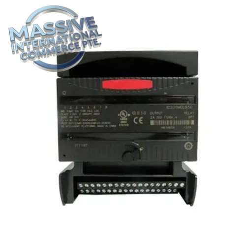
- Model: IC200MDL930J-700, base part IC200MDL930
- Brand: GE Fanuc
- Part Type: VersaMax isolated relay discrete output I/O module
- Lifecycle status: OEM obsolescent, stocked for brownfield VersaMax control racks
- System compatibility: VersaMax CPU and I/O carrier bases
- Weight: 0.24 kg
Technical Introduction
Process equipment stops responding to PLC commands when this relay output module fails. This carrier-mounted module provides eight individually isolated Form A normally open relay contacts. Each channel can switch AC or DC loads up to 2A, separating field power circuits from the VersaMax backplane logic. Every output channel has a dedicated status LED to simplify point troubleshooting. Module operating power draws from the rack backplane; load power is sourced externally on the field side. Batch and discrete manufacturing plants hold this spare to reduce downtime while evaluating legacy PLC migration.
- Best Suited For
- Solenoid valve and small contactor actuation
- Alarm beacon and local panel indicator control
- Direct drop-in replacement for existing IC200MDL930 series hardware
Core Technical Specifications
| Parameter | Value |
|---|---|
| Part Number | IC200MDL930J-700 (base IC200MDL930) |
| Series | GE Fanuc VersaMax |
| Output Type | 8 × Individually Isolated Form A (NO) Relay |
| Per Channel Rating | 2A resistive |
| Switching Voltage | Up to 250VAC / 30VDC |
| Backplane Current Draw | 180 mA @ 5VDC |
| Isolation | Channel-to-backplane isolation |
| Indicators | 8 individual channel status LEDs |
| Weight | 0.24 kg |
| Environmental Details | Please refer to the OEM datasheet for complete environmental tolerances. |
Field Engineer’s Tech Notes
- Relay contacts degrade quickly with inductive loads such as solenoids without snubber protection. Add RC snubbers across inductive loads to extend contact service life and reduce electrical noise into the I/O rack.
- Hot-swap is not recommended on older VersaMax carrier and CPU firmware. Removing the module while rack energized can trigger backplane communication faults and corrupt active I/O mapping.
Adaptive QA & Testing Protocol
Each module installs on a VersaMax carrier bench fixture. The PLC is programmed to toggle each relay channel on/off sequentially. We verify LED status and measure contact continuity with a multimeter for every point. We confirm isolation between each relay channel and the module backplane circuit. Full test reports or bench test video clips are available upon request.
Buyer’s FAQ
Q: What does J-700 suffix mean on IC200MDL930J-700? A: The suffix marks hardware revision and manufacturing batch variant. Pinout and core relay function match base IC200MDL930, but cross-check marking against your installed unit before swap.
Q: What warranty applies for refurbished and NSFP IC200MDL930J-700? A: Refurbished and NSFP units carry a 12-month hardware warranty. Coverage excludes contact damage caused by unprotected inductive loads or overcurrent on field wiring.
Q: What lead time should I expect? A: Stocked units ship 3–7 business days. If inventory is depleted, lead time increases while we source available surplus relay I/O modules.
Q: Can this module switch high current motor loads directly? A: No, rated for 2A resistive only. Use these relay outputs to drive intermediate contactor coils, not motor power circuits.

 Start Chat


 Send an Email


