
Description
Product Overview
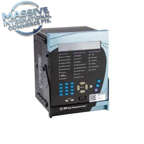
The GE Multilin 469-P1-HI-A20 is a draw-out digital motor management relay from GE Multilin 469 series, designed for comprehensive protection, metering, control and diagnostics of medium & large three-phase industrial motors. The suffix P1 represents 1A CT secondary input, HI denotes high control power range, A20 means 4–20mA analog output. It integrates thermal overload model, motor starting protection, single CT differential protection and RTD temperature monitoring. Widely used in MCC motor control centers, oil & gas, chemical, power plant, water treatment and mining facilities, it can connect to DCS/SCADA via serial or Ethernet communication for motor condition monitoring and fault event recording.
Technical Specifications
| Item | Parameter |
|---|---|
| Part Number | 469-P1-HI-A20 |
| Manufacturer | GE Multilin (General Electric) |
| Series | Multilin 469 Motor Protection System |
| Product Type | Draw-out Motor Management Relay |
| CT Secondary Input | 1 A phase CT |
| Control Power (HI) | 70~265 VAC / 90~300 VDC, 48~62 Hz |
| Analog Output | Four 4–20 mA outputs (A20 version) |
| RTD Input | Multiple 3-wire RTD inputs (Pt100, Ni100, Ni120, Cu10) |
| Digital Input | 9 opto-isolated discrete digital inputs |
| Relay Output | 8 programmable form-C contact outputs |
| Display | Backlit LCD + local keypad for onsite setup and readout |
| Communication | Modbus RTU, Modbus TCP, Ethernet |
| Mounting | Panel mount / MCC drawer draw-out construction |
| Operating Temp | -40°C ~ +60°C |
| Storage Temp | -40°C ~ +85°C |
| Humidity | 5–95% non-condensing |
| Enclosure Rating | Front IP40, rear IP20 |
| Configuration Software | EnerVista 469 Setup Software |
| Hot Swap | Draw-out unit allows removal without de-energizing cabinet wiring |
Key Features
- Complete motor protection suite: thermal overload, locked rotor, phase loss, phase unbalance, overcurrent, undervoltage, overvoltage and single CT differential winding fault protection.
- High precision thermal model, combined with multi-point RTD winding & bearing temperature monitoring, accurately calculates motor thermal capacity and prevents premature insulation aging.
- Draw-out modular construction, the relay core unit can be pulled out for maintenance or replacement without disconnecting field CT/PT wiring.
- Built-in fault waveform capture, event log and motor start trend recording for post-fault root cause analysis.
- 4 channels of isolated 4–20mA analog outputs to transmit motor current, temperature, power and other real-time parameters to DCS and SCADA.
- Multiple opto-isolated DI/DO points for local interlock, motor start/stop control and alarm contact output.
- Multi-protocol communication support for seamless integration into plant control network; parameters can be set locally via keypad or remotely by EnerVista software.
- Optional conformal coating variant available for corrosive, high humidity industrial environments.
Installation Notes
- Install 469-P1-HI-A20 relay inside MCC drawer or control panel, maintain adequate ventilation space for heat dissipation.
- Confirm CT ratio is 1A type, do not match with 5A CT (P5 model). Verify control power voltage before power up.
- Separate CT/PT high-current wiring, power cables and low-level RTD/communication signal wiring to reduce electromagnetic interference.
- Follow lockout/tagout procedure before opening panel or pulling out relay unit.
- Backup relay setting file via EnerVista software before replacement or firmware upgrade.
- After installation, perform CT polarity check, input/output loop test and protection curve verification before putting motor into service.
- Wire RTD sensors with 3-wire cable to minimize lead resistance measurement error.
Testing Procedure
- Visual inspection: Check housing, LCD screen, keypad, terminal block and connectors for cracks, burn marks or corrosion.
- Mount relay into MCC drawer, wire CT, RTD, control power and I/O connections. Apply rated control power and check power-on self-test.
- Inject simulated secondary current and voltage signals, verify metering reading on LCD and EnerVista software.
- Test RTD channels with resistance simulator to validate temperature measurement accuracy.
- Trigger protection functions (overload, phase unbalance, overcurrent) to check relay trip action and event log recording.
- Verify 4–20mA analog output scaling and digital input / relay output contact operation.
- Save relay setting file, record all test results and tag spare relay for inventory.
FAQ
Q: What is GE 469-P1-HI-A20 used for? A: It is a GE Multilin motor management relay for medium voltage three-phase motors, offering protection, control, temperature monitoring and data communication in MCC and industrial motor control systems.
Q: What does P1 mean in part number? A: P1 means 1 Ampere CT secondary input, while P5 variant is for 5A CT.
Q: What is the difference between A20 and A00? A: A20 = 4–20mA analog output; A00 = 0–1mA analog output version.
Q: What software configures this relay? A: EnerVista 469 Setup software for parameter configuration, firmware update, waveform and event log review.

 Start Chat


 Send an Email


